На русском
After the last unsuccessful attempt at building this thing, I've finally got it working.
Some helpful tips:

|
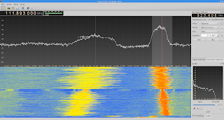
| Normal output (note the awful frequency drift-off) |
|

|
| Output with base overdriven |
|
|
| Signal's doppelganger to the left |
- Things like size of the pads (exactly 5x5 mm.), lead length (minimal) and component placement really DO matter. If you assembled a transmitter like this one and it doesn't seem to work (or it does, but the signal is noisy with lots of out-of-band emissions) you probably should check the layout.
- Signal frequency drifts off with decrease of battery voltage, and really fast. Therefore, it's not practical to use transmitter as it is now. One should add a voltage regulator to power the circuit in order to stabilize output frequency.
- Too large of an amplitude of the signal will saturate the transistor's base and "bloat" the output frequency band, rendering the sound almost unrecognizable.
- Almost any sort of transistor will do, such as renowned 2N3904. Look in the datasheet for fT (Current Gain - Bandwidth Product). It shouldn't be less than 170MHz (Kogawa himself uses 2SC2001 with this figure, 2N3904 is even better with 300MHz).
- The transmitter, other than the intended RF signal, will produce it's weakened undesired copies outside the band. Search for the strongest signal.
To-do:
- Stabilize the power supply to prevent frequency drif-off (add a simple 7809 voltage regulator and increase the power supply voltage).
- Add band-pass filter at the output to supress out-of-band noise.
- Add antenna to invade the neigborhood! 🎉


Comments
Post a Comment